Part of AEC Industry Collection subscription
Grading Optimization is an AI-based program that takes your design elements building pads, drainage lines, etc. adds your design constraints, and produces a best-fit finished-ground surface model with feature lines.
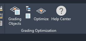
To access the Grading Optimization ribbon, go to the Analyze tab and then find the Grading Optimization panel at right end.

Grading Optimization has three parts. When inside the Civil 3D environment, you will use the Grading Objects Tools tool palette to convert your AutoCAD polylines into Grading Objects.

Grading Objects Tools
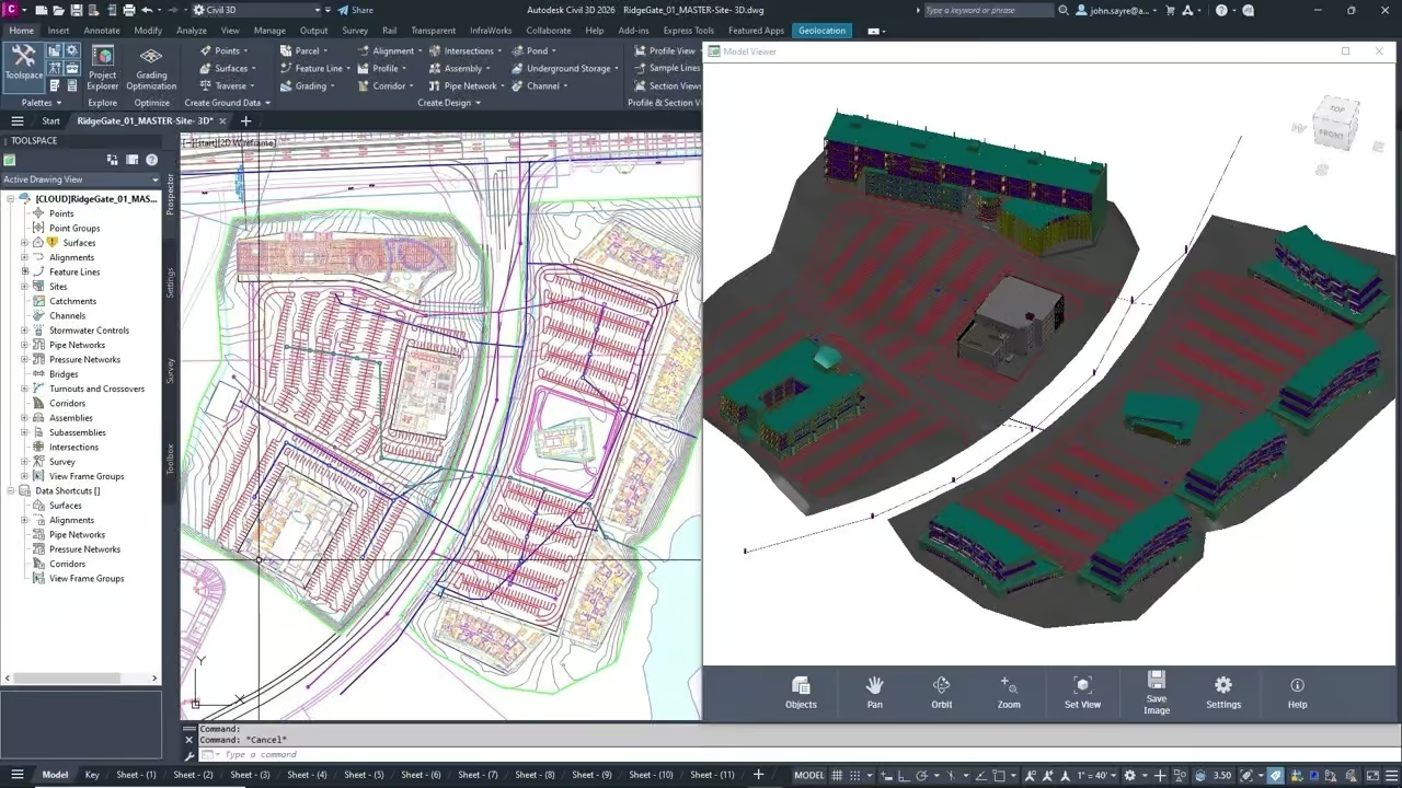
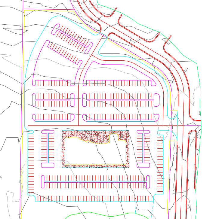
Here, we have a hotel site, where we have already outlined the parking area and building envelope using AutoCAD 2Dpolylines. A detention pond has been outlined and there is an existing ground TIN Surface.
Next, from the Grading Optimization Tool Palette, we assign a Building Pad to the Polyline that was sketched for the building pad location.
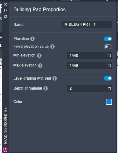
Creating a Grading Object triggers Grading Properties dialog to appear. Here is where you set constraints for this object. In the case of a Building Pad, you can set minimum and maximum elevations to be considered as the design is iterated. If you already know the finished floor elevation you want, you can turn on Fixed Elevation Value.
After having created the Building Pad, any time that you select the polyline, the Grading Properties will appear, allowing you to edit your constraints. Add Drain Lines, Curbs, Ponds, Retaining Walls, etc, and assign their constraints.
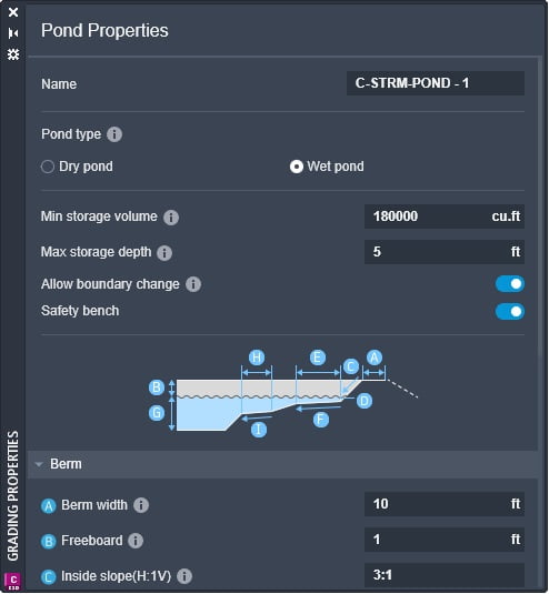
Different objects will have different constraints listed in Properties. For example, a Building Pad has just a few parameters, while a Pond has many. This screenshot shows about half of them.
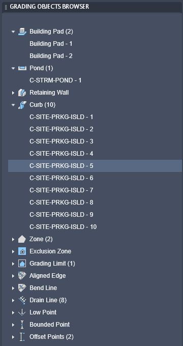
Grading Objects Browser
The Grading Objects Browser automatically populates to list any Grading Objects you have placed in the drawing. Select one to edit its properties.
Optimizer
The Optimizer is an interface that runs outside Civil 3D, and which iterates the best design solution to match your grading objects and their constraints.
This is the Optimizer interface:
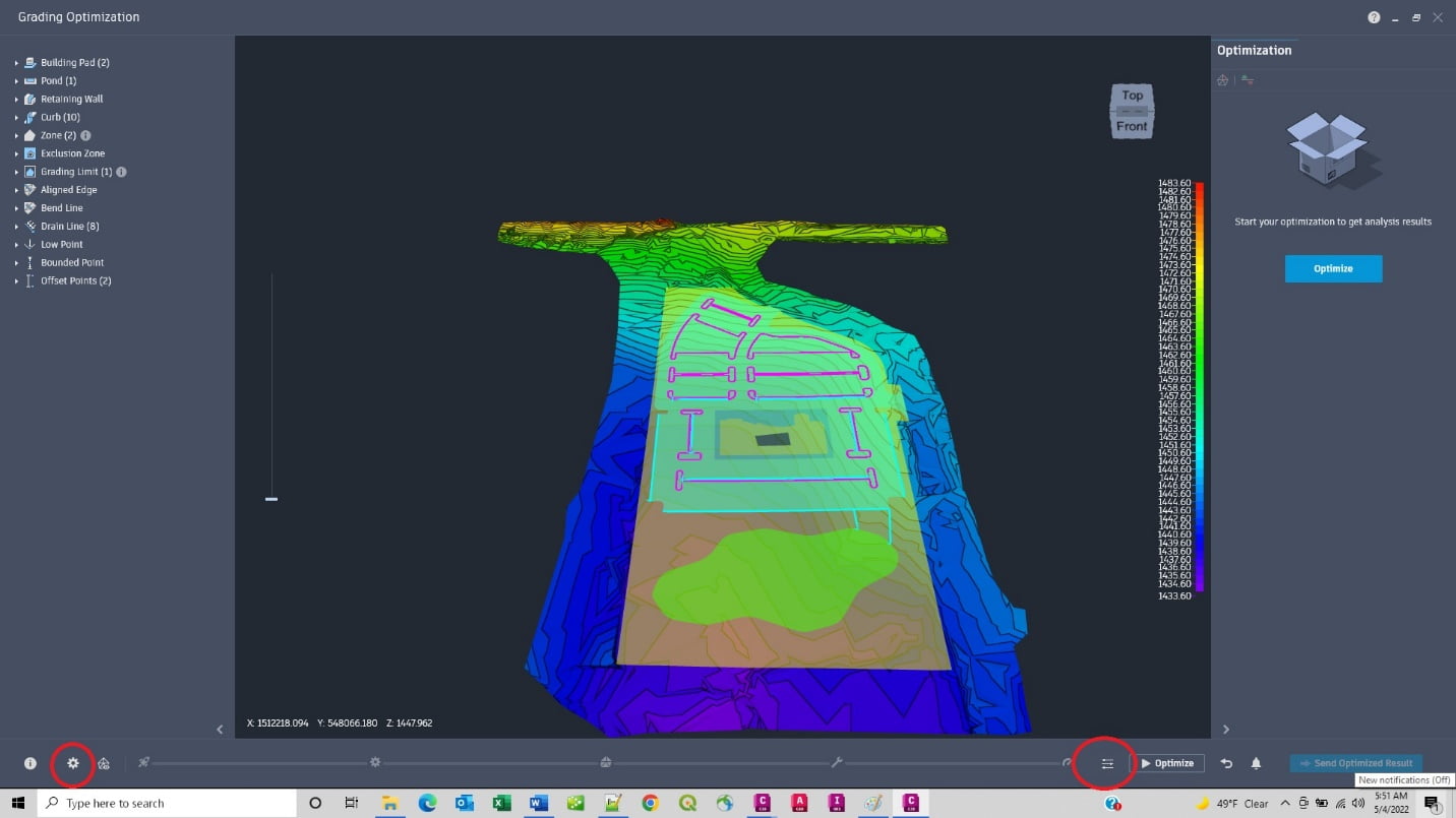
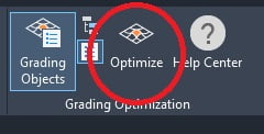
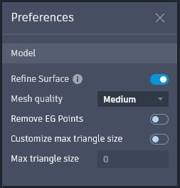
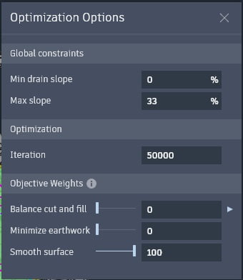
Note these two important buttons: Preferences and Optimization Options, circled in red, above.
Preferences lets you choose to refine the design surface. Optimization Options allows you to set the number of iterations, as well as to set weighting for design objectives like Cut and Fill Balancing and minimizing Earthworks.
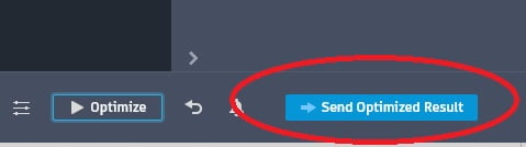
Once you’ve set Preferences and Optimization Options, press Optimize.
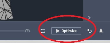
The optimizer will iterate up to the number of iterations you set. If you set a low number, it will finish faster, but give less-refined results. A higher number of iterations will give better results, but can take considerable time. You can Stop optimization at any point, and send the “so far” results back to Civil 3D.
Coming back to Civil 3D will be Surfaces, Feature Lines and Points.
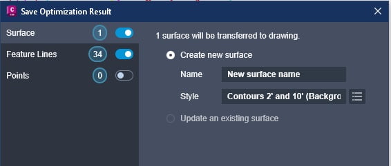
If you select Feature Lines in the list on the left side of the dialog, you can create a new Site, merge these Feature Lines into an existing Site or bring them into the ‘Feature Lines’ collection, where they are considered “siteless.”

When the import completes, the Surfaces, Feature Lines and Points become regular Civil 3D objects in your drawing.